Last post is about overview of Epson WF-C579, WF-C529 Inksystem mechanism, click here
This post is the details of the Operation of each mechanism of Inksystem on Epson WF-C579, WF-C529.
– To know more about Epson WF-C579, WF-C529 Operating Principles, click here
– To know more about Installation on Epson WF-C579, WF-C529, click here
Epson WF-C579, WF-C529 Inksystem – Pump Mechanism
The pump mechanism sucks ink from the Printhead at cleaning.
The drive force from the Pump-drive Compound Gear is transmitted to the pump shaft via the Timing Plate. This Timing Plate allows the Pump-drive Compound Gear to start rotating at the different timing from the Pump Shaft.
After the PF Motor rotates for a while, the Pump Unit starts its operation.

When the Pump Motor rotates counter-clock wise as seen from the output-shaft side of the motor, the drive force via the Pump-drive Compound Gear rotates the Pump Pulley to flatten the tube to suck the air (to generate negative pressure) inside the tube.
When the Pump Motor rotates clock wise, the Pump Pulley does not flatten the tube, and the negative pressure is released.

– Pump Unit contains: Pump Spacer, Pump Shaft, Pump Pulley, Pump Cam, Pump Frame, Pump Tube, Pump Spring, Timing Plate, Pump-drive Compound Gear
Furthermore, this products incorporate two pumps, with improved suction performance.
Epson WF-C579, WF-C529 Inksystem – Cap Mechanism
The direct acting type is employed in the capping mechanism, where the Cap is moved up and down by the Pump Motor and the Printhead is capped at the suction for cleaning.

Intermittent Gear 2 rotates on drive power from the Pump Motor, and the cam surface on the Intermittent Gear 2 pushes the Cap, moving it forward. At this time, the cap tab contacts the Printhead surface, guiding the Printhead on the Cap.
Next, the Wiper/cap-drive Cam moves the Cap Drive Lever, raising the Cap, capping the Printhead.

The cam surface (in red) of the wiper/cap-drive cam raises and lowers the cap drive lever.
— Epson WF-C579, WF-C529 Ink leak detection, click here
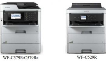
— Epson WF-C579R, WF-C579Ra, WF-C529R Structure and Configuration, click here
Epson WF-C579, WF-C529 Inksystem – CR Lock Mechanism
The tension of the compression spring at the bottom of the CR Lock moves up the CR Lock. When the CR Lock Drive Lever pushes the CR Lock downward, the CR Lock is released.

Since the CR Lock Drive Lever moves up and down together with the Cap Drive Lever, the CR Lock also operates together with the movement of the Cap. This means that the printhead nozzle surface is always capped when the CR Lock is set.
Epson WF-C579, WF-C529 Inksystem – Wiper Mechanism
The rotation of the Wiper/cap-drive Cam drives the wiper mechanism.
After release of the capping, if the Wiper Cam rotates, the drive is conveyed to Wiper Gears 1, 2, and 3, and the Wiper moves along the CR unit path.

Epson WF-C579, WF-C529 Inksystem – Venting Valve

– The rotation of the Wiper/Cap Drive Cam moves the salient of the Wiper Drive Lever along the cam surface of the Wiper/ cap-drive Cam (red part) to move the valve open and close
Before capping, the Valve Lever interferes with the Link Lever, therefore the Venting Valve opens.
During the capping sequence, the Valve Lever shaft moves along the Wiper/ cap-drive Cam Slot, and the Valve Lever drops backwards. When this happens, the Valve Lever and Link Lever interference is removed, and the return force of the Compression Spring makes this slide to the 80-digit side, closing the Venting Valve.
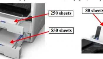
–Epson WF-C579, WF-C529 Paper Loading, Paper Feed mechanism, click here
–Epson WF-C579, WF-C529 Paper Loading, Paper Feed mechanism details, click here