Continue from the last post about Epson WF-C579, WF-C529 Paper Loading, Paper Feed mechanism, click here
This post is the details with each steps about the Epson WF-C579, WF-C529 Paper Loading, Paper Feed mechanism
— To know more about Epson WF-C579, WF-C529 Operating Principles, click here
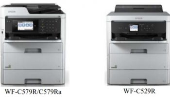
Epson WF-C579, WF-C529 Printer Main Unit mechanism
Lift-up mechanism
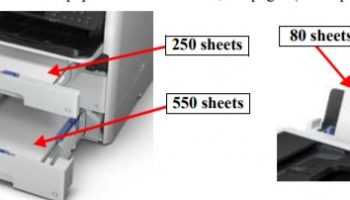
This mechanism lifts up the paper set in the paper cassette up to the paper pickup position by the pickup mechanism.
The lift-up mechanism operates the Cassette Hopper by the force of the spring provided inside the Paper Cassette.
When the Paper Cassette has been removed from the printer, the Cassette Hopper is locked by the Hopper Lock present in the center part and the Hopper
Stopper on the left and right sides.

When you set the Paper Cassette in the printer, the Hopper Lock and Hopper Stopper of the Paper Cassette come in contact with the Release Rib, and the lock is released. The released Cassette Hopper rises due to the tension of the spring.
Front Feeding Mechanism
The front feeding mechanism is composed of the Pick-up mechanism and the intermediate feeding mechanism.
– Pick-up mechanism:
This mechanism picks up paper from the Cassette Assy and feeds it up to the intermediate feeding mechanism. The retard separation method is used for paper separation.
The ASF Motor drives the pick-up mechanism. The pickup roller and separation roller uses a one way clutch to always rotate in a set direction (paper feed direction) only. When the ASF Motor rotates the opposite direction of paper feeding, the drive force is cut off by the One Way Clutch, so neither the Pick-up Roller nor Separation Roller rotates.

ASF Motor => Compound Gear A => Compound Gear B => Pickup Drive Shaft A => Spur Gear16.8 => Spur Gear 15 => Spur Gear 16.8 => Spur Gear 15 => Pickup Roller/Separation Roller => One Way Clutch => Pickup Roller/Separation Roller
— More information about Epson WF-579R, WF-579Ra, WF-529R Operating Principles, click here
— Epson WF-C579, WF-C529 Printhead Operating principles, click here
– Intermediate feeding mechanism
This mechanism feeds the paper fed from the Cassette Assy to the paper feed mechanism.
The intermediate feeding mechanism is driven by the ASF Motor.
The Middle Roller always rotates in a set direction (paper feed direction) because of the Planet Gear, regardless of the ASF motor rotational direction.

ASF Motor => Compound Gear A => Planet Gear => Compound Gear 35.5, 26.4 => Duplex Gear =>Middle Roller
Rear Feeding Mechanism
– Overview
This mechanism feeds the paper set on the Hopper to the intermediate feeding mechanism. The retard separation method is used for paper separation.
The rear feeding mechanism is driven by the ASF Motor.
Since the ASF Motor drives the pick-up mechanism and intermediate feeding mechanism, the ASF Clutch Gear and Rear ASF Solenoid Assy turn the drive force ON/OFF so that the LD Roller rotates during the rear feed only.

ASF Motor => Compound Gear A => Compound Gear C => Planet Gear => Compound Gear 35.5, 26.4 => Compound Gear D =>Spur Gear => Rear ASF Solenoid/ASF Clutch Gear operation => LD Roller
– Operation of the rear feeding mechanism
- # Drive force control by the ASF Clutch Gear and Rear ASF Solenoid Assy
The Rear ASF Solenoid Assy controls the operation of the Change
Lever by electrifying the Solenoid.1 The relationship of the electrifying
status of the Solenoid and the status of the Change Lever is as follow.
When the Change Lever engages with (or locks) the hook on the ASF Clutch Gear, the clutch of ASF Clutch Gear is cut off and the ASF
Motor’s drive force is not transmitted to the LD Roller.
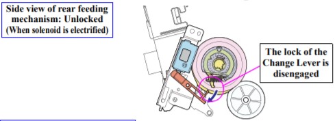
When the Change Lever releases (unlocks for driving the rear feeding) the hook on the ASF Clutch Gear, the clutch of ASF Clutch Gear
engages and the ASF Motor’s drive force is transmitted to the LD Roller - # When performing the rear feed
When the printer starts performing the rear feed, the Solenoid of the Rear ASF Solenoid Assy is electrified and the Change Lever is moved down to unlock the hook. Then the clutch of the ASF Clutch Gear engages and the drive force of the ASF Motor is transmitted to the LD Roller. After the lock is released, the ASF Motor drives the ASF Clutch Gear and LD Roller to move the hook on the ASF Clutch Gear away from the lock position.
Therefore, when electrifying the Solenoid is stopped and the Change Lever is back to the original position, the hook on the ASF Clutch Gear is positioned lower than the Change Lever due to the rotation of the LD Roller and not going to be locked again.
After electrifying the Solenoid is stopped, the ASF Motor rotates clockwise further and the LD Roller rotates in the paper feed direction.
A sheet of paper set on the Hopper is separated by the LD Roller and Retard Roller and fed to the intermediate feeding mechanism - When the LD Roller rotates once, the Change Lever engages with the hook on the ASF Clutch Gear and the roller is locked. Then, the ASF Motor’s drive force to the LD Roller is cut off and the rear feed process is completed
- Side view of rear feeding mechanism: Locked (When solenoid is not electrified)

-
- Side view of rear feeding mechanism: Unlocked (When solenoid is electrified)
-
- Side view of rear feeding mechanism: When rear feed is driven (When solenoid is not electrified)

— Epson WF-C579, WF-C529 Carriage Mechanism, click here
Paper Feed Mechanism
This mechanism feeds the paper fed from the intermediate feeding mechanism and ejects it.
The paper feed mechanism is driven by the PF Motor’s drive force. The drive force of the PF Motor is transmitted by the PF Timing Belt to the PF Roller and EJ roller to perform paper feeding before/after printing.

PF Motor => PF Timing Belt => PF Roller => Spur Gear 28.8 => Spur Gear 49.32 => Spur Gear 21.1 => EJ Roller
— Epson WF-C579, WF-C529 printer’s Other Motor and Sensors, click here
— Epson WF-C579, WF-C529 printer’s Sensors, click here